A lifetime of rowing has left me dissatisfied with the oarlocks I have been using. Some broke, some bent, most wore out the oar, all wore out the socket and pin, some were easily lost and most were heavy. In time many rusted and after some use, the excessive wear caused two clunks with each stroke. To insert the oarlock into the socket it often had to be returned from the blade end by raising the oar till the oarlock came crashing down to the button (oarstop).
It is interesting to consider the degrees of freedom an oarlock must allow an oar. The oar must be able to:
- Move in a horizontal plane.
- Move in a vertical plane.
- Rotate.
- Be withdrawn.
- Be removed from the gunwale.
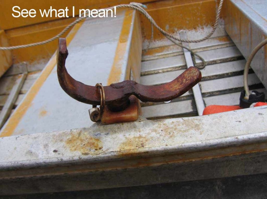
The clunking rowlock: The excessive wear on the socket and upper part of the pin is easily seen as an engineering fault. The pin rotates in the socket, which becomes the bearing. The problem is that the pin exerts an uneven and excessive pressure at the top of the socket, so wear is concentrated there and to a lesser extent at the bottom of the pin and socket.
Before long the oarlock clunks backwards and forwards with each stroke.
This problem is solved by designing an oarlock that rotates on the pin with the pin remaining fixed in the socket. You may wonder why this issue has not been addressed in the past.
In the middle of the last century, it was my habit as a child to bail out the hire boats at the local boatshed and as a reward take one for a row. One particular type of oarlock stuck in my memory as it was mounted on a fixed post and was of a D-shape. I have managed to track some down at a maritime collection in Tasmania. In the little hamlet of Tinderbox, Ross Burnett has a collection of clinker rowing boats, oars and oarlocks including the type described. A company associated with Kopsens in Sydney used to make these. It has a bolt around which the bronze horn rotates and the wear is evenly distributed on the bearing surfaces. Often the bolt was steel and if properly maintained, was also greased. Too bad if not, as rust would quickly foul things up.
This oarlock was fine for hire boats as it was strong, resisted wear and could not be lost. However for modern skiffs it could cause damage to itself and the deck whilst upending the craft, and would be inclined to gouge the side of any yacht that it pulled alongside.
Another variant of this has been supplied from a boatshed belonging to an old water access house on the Hawkesbury River. Shown below, this rugged design weighs just over one kilogram (2 ¼ pounds). Rowers designed this in the first half of the twentieth century to solve the problem of rowlock wear on boats used for transport rather than as a tender.
Bearings work best when one surface is softer and bronze on bronze can become squeaky if not greased as would often be the case.
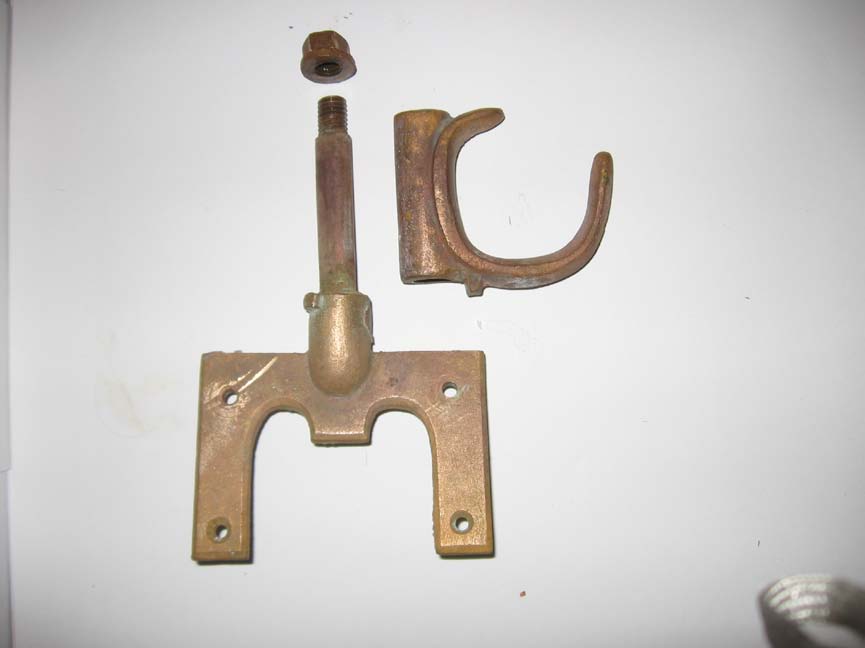
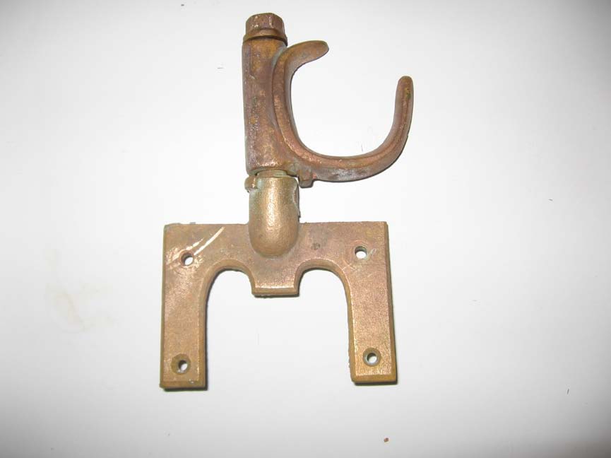
Table of Contents
Oar wear:
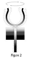
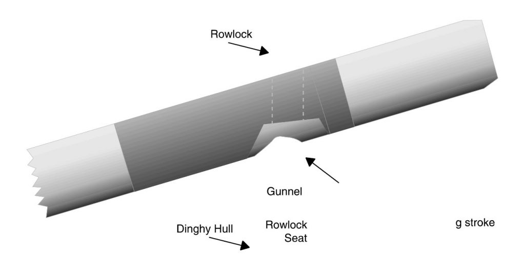
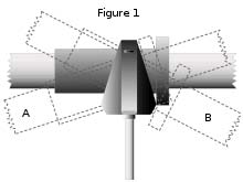
There is another aspect of oarlock design that is not properly understood. Much of the wear on an oar appears on the underside instead of the back of the shaft where it bears on the oarlock. As the blade is lowered into the water during the stroke the top of the button bears against the top of the oarlock. The bottom of the shaft is then dragged across the bottom of the oarlock, persistently wearing it away. The diagram below illustrates this process.
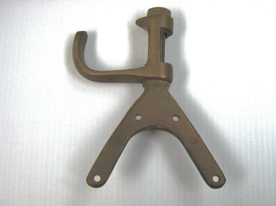
Below is an extraordinary and beautiful design of oarlock. This was dredged up in St.Nazaire in France and the photographs and details passed on by a Dutchman Mr. Cor En Leen. He and his colleagues are inclined to think it was a gun-holder but there are too many features distinguishing it as an oarlock. Some may argue that it was for a sweep but I suspect that a sweep or a gunholder for that matter, would have its pin in the centre.
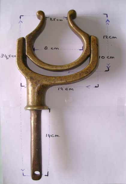
This oarlock deals with the vertical friction and wear very effectively. It weighs two kilograms (over four pounds) has a ¾” pin. It will accommodate a three inch diameter oar which happens to be about the size of a whale-boat oar. Notice how the oar can only be fitted and extracted at the blade end and is thus less likely to be lost, but this did not stop some cursed soul losing this oarlock overboard. However a simpler way of resolving this wear problem has already been in use.
In my quest for a better design I began investigating use of the racing oarlock. Much to my disappointment I found that they were the wrong diameter, were quite expensive and were designed to slip over a post bolted to the outrigger. However the general principal on which the bearing functioned was much superior from the point of wear and friction. Thus I found myself making a variant that could be used on the Herreshoff rowboats that I make. These worked well and are still in use today 20 years later, but they were a lot of work and missed some features.
Careful study of the racing oarlock revealed a profile that eliminated the friction cause by vertical motion. This lead me to make some wooden mock ups to perfect the ideal profile. The diagram below illustrates how this works. I discovered that the widest part of the profile should coincide with the bottom of the oar in the oarlock, a fine point that the racing oarlock seemed to have missed. The oar had to pivot over a triangular profile at the bottom of the oarlock.
This is not the only way of solving this problem. I have never seen it practised, but I suspect that an outward angle equal to the angle the oar makes with the water (about 150) on a conventional oarlock would solve the problem. If this seems a bit extreme any outward angle will help.
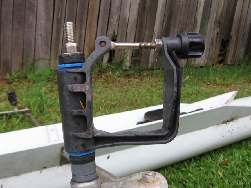
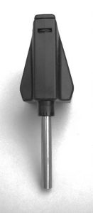
Astonishing technology: I engaged an Industrial Designer to draw up a Cad- Cam (Computer Aided Design-Computer Aided Manufacture) model employing the features mentioned above. Over a period of a year of experiment and in consultation with a Mechanical Engineer and the Industrial designer we came up with the final model oarlock. Significant contributions by this loosely knit team enabled the use of a catch that not only captured the oar but also the pin.
The rest of the process was astonishing. It took place in several stages.
An exact replica of the CAD was cut out of graphite using a CNC (Computer Numeric Control) lathe.
This was then immersed in kerosene above metal slab that was to become the mould.
An electric field was created between the graphite replica and its exact shape was etched into the mould.
A trial run was completed with two plastics, nylon and polypropylene. The nylon proved unsatisfactory as it was too stiff and changed its properties markedly when wet.
This may sound simple but many costly and troubling problems were overcome before getting to market. However the oarlock has lived up to, and in some respects exceeded expectations.
Some have argued that the pin would revolve in the socket. However the oarlock chooses the bearing surface with the least friction and revolves around the upper part of the pin. Inspecting the pin after some use confirms this fact.
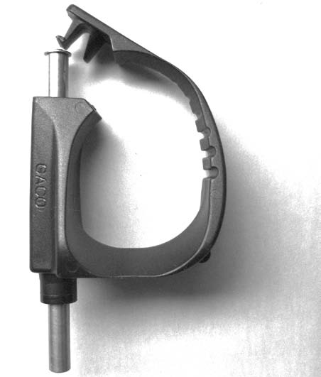
The 10mm (slight larger than 3/8”) hardened 316 stainless steel pin and plastic body enable a much lighter oarlock. We have found on the surfboat that even when one man is on an oar it will not bend the pin. None, including those hand made, have worn one out after 20 years of regular use.
Oh! Some customers wanted to use their existing sockets so an interference fit sleeve was developed for 7/16” and 1/2″ sockets.
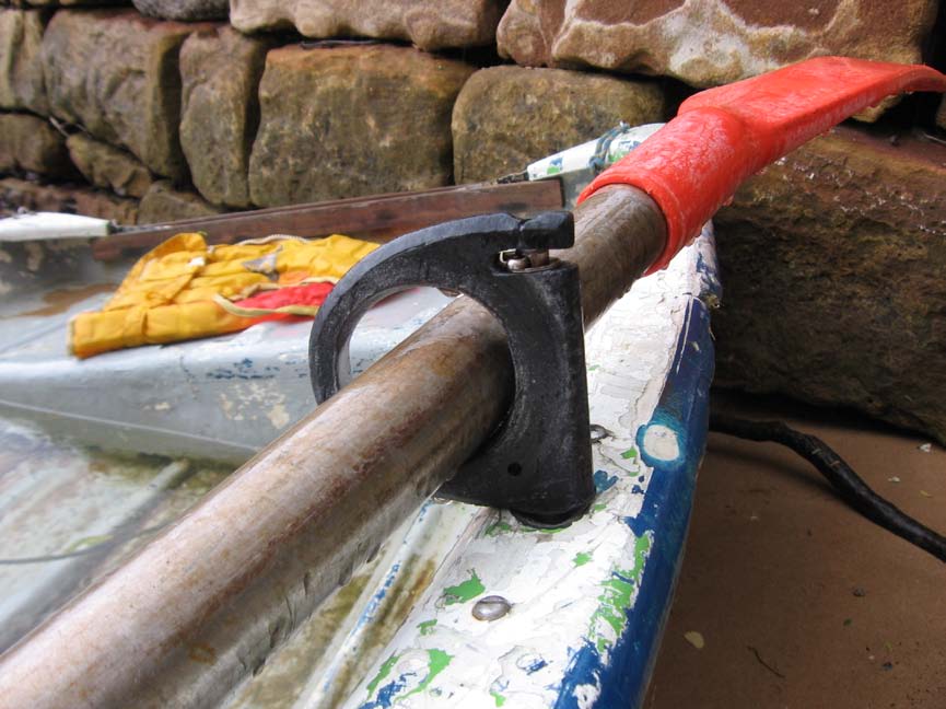
Some unanticipated bonuses have revealed themselves. For instance it is possible to rasp the oarlock to fit particular designs of oars. Also being plastic the oar-holder is much kinder to oars and the oarlock is significantly lighter than all other oarlocks except the all plastic models.
The oarlocks have been on the market for eight years now and are being sold in the US, Australia and New Zealand. Individuals have ordered them from the UK and Sweden.
Website reviews have generally complimentary of their silence, and the ease with which they work. One bloke even gave up using his outboard in favour of rowing. Being a bit of a greenie, that is one result I endorse.
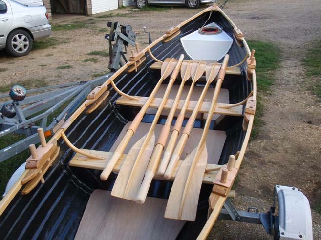
Now that this task was complete I took it upon myself the job of making a better oar since those available were either specific for racing craft and expensive, or designed for cheapness.
Postscript:
A customer in the UK has tried thole pins in the 18 foot gig he had built by Chris Rees. Traditional as they are he found the Gaco very much better “perfect” as he described them